Dynamic Methodology
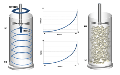
The FT4 Powder Rheometer employs unique technology for measuring the resistance of the powder to flow, whilst the powder is in motion. A precision ‘blade’, or impeller, is rotated and moved downwards and upwards through the powder to establish a precise flow pattern. This causes many thousands of particles to interact, or flow relative to one another, and the resistance experienced by the blade represents the difficulty of this relative particle movement, or the bulk flow properties. The more the particles resist motion and the harder it is to get the powder to flow, the more difficult it is to move the blade.

As the blade moves through the sample, the FT4 measures both rotational and vertical resistances, in the form of Torque and Force respectively. It is important to capture both signals as it is the composite of these two values that quantifies the powder’s total resistance to flow.
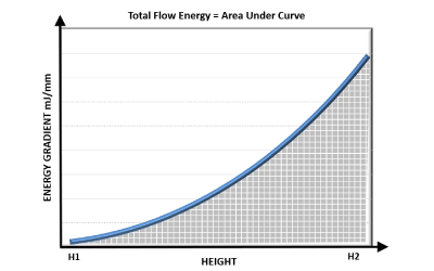
Using the calculation of WORK DONE, it is possible to represent both the Torque and Force signals as a Total Flow Energy, the energy required to move the blade through the sample from the top to the bottom of the powder column. However, because the values of torque and force are constantly changing, it is necessary to calculate the energy for each small distance travelled. This is the calculation of Energy Gradient, the energy measured for each millimetre of blade travel, expressed in mJ/mm.
Work Done = Energy = (Resistance x Distance travelled)
where ‘RESISTANCE’ is the combined Torque and Force
Energy Gradient = Energy per mm of blade travel
Calculating the area under the Energy Gradient curve provides the Total Flow Energy, representing the powder’s resistance to being made to flow in a dynamic state.

Energy Gradient is calculated directly from the measurements of Torque and Force
Confined and Unconfined Powder Flow
Two types of powder flow pattern are typically employed for quantifying flowability: -
Forced (or confined) Flow
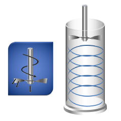
A measure of the powder’s flowability when forced to flow, such as through a screw feeder or in an active feed frame. This property is defined as the Basic Flowability Energy, BFE, and is measured during the downward blade movement. The powder is confined by the closed bottom end of the test vessel.

Direction of movement downwards
Low Stress (or unconfined) Flow
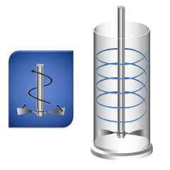
A measure of the powder’s flowability when unconfined, such as during low stress filling, or low shear blending. This property is defined as the Specific Energy, SE. In this measurement, the resistance to flow is measured as the blade traverses from the bottom of the vessel to the top. As there is no solid surface at the top of the vessel preventing the powder from dilating and moving upwards, the powder is unconfined during this test.

Direction of movement upwards
The regimes of confined and unconfined flow are very different and so it is important, when correlating data with process performance, to identify which regime is most representative of the process being considered.